- Horton C2150 Controller Programming Manual Software
- Horton C2150 Controller Programming Manual Download
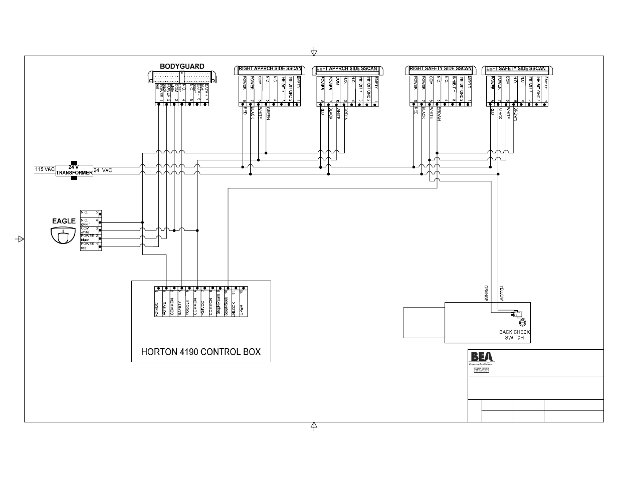
EAGLE
USER GUIDE
1 Description
Related Manuals for Horton C No related manuals. Test -To maintain security,battery failures are ignored in the night mode,but the failure hoorton stored on the units circuit board. Actuation Features During initialization the control clears all ports and the solenoid becomes inactive. Got it, continue to print. After making changes, press RESET to exit program mode The control will perform a learn cycle on the first activation after a reset DC One V3 Installation Manual M-0015 REV 05212015 P8 Page 6 of 15 13.
Terminal | Narrow Antenna Storage | Manual Set-Up Buttons | Wire Opening Knockout | Opening Tab |
Block | (inside the cover) |
Wire Passage Hole | Planar Antenna | Lateral and Angle | Front Cover | LED |
Adj. For Antenna |
NOTE: For mounting heights between 10' and 16', use BEA model 10EAGLEHM (high mount).
2 | Technical Specifications |
DESCRIPTION | SPECIFICATION |
Frequency: | 24.125 GHz |
Supply voltage: | 12 to 24 V AC: ± 10%: |
12 to 24 V DC: -10% / +30%: | |
Mounting height: | Normal: 7'; Maximum: 10'-0' |
Tilt angle: | 0° to 90° vertical |
-15° to +15° lateral | |
Detection area: | 13ft (W) x 6.5ft (D) |
Wide | |
Narrow | 6.5ft (W) x 8.2ft (D) (supplied as optional) |
Minimum detection speed: | 2 in/sec. (measured in axis) |
Power consumption: | < 2 W |
Converter iso para elf ps2. Standard output relay: | |
Max contact voltage | 60 VDC / 125 VAC |
Max contact current | 1 A (resistive) |
Max switching power | 30W (DC) / 60VA (AC) |
Hold time: | 0.5 sec. to 9 sec. (adjustable) |
Temperature range: | -4°F to 131°F |
Dimensions: | 4.75in (W) x 3.15in (H) x 2.0in (D) |
Weight: | 0.5lbs |
Material: | ABS |
Housing color: | Black. Can be painted with non-metallic paint |
Cable length: | 6ft |
75.5185.04 20070727 | Page 1 of 8 Ide app download. |
1 Tips
The sensor must be firmly fastened to prevent vibration.
The sensor must not be placed directly behind a panel or any kind of material.

The sensor must not have any object likely to move or vibrate in its sensing field.
The sensor must not have any fluorescent lighting in its sensing field.
Substance designer 2019 3 3 turbo. 2 Safety Precautions
Autodesk maya 2009 keygen. •Shut off all power going to the header before attempting any wiring procedures.
•Maintain a clean & safe environment when working in public areas.
•Constantly be aware of pedestrian traffic around the door area.
•Always stop pedestrian traffic through the doorway when performing tests that may result in unexpected reactions by the door.
•Always check placement of all wiring and components before powering up to insure that moving door parts will not catch any wires and cause damage to equipment.
•Ensure compliance with all applicable safety standards upon completion of installation.
ELECTROSTATIC DISCHARGE (ESD) PRECAUTIONS
Circuit board components are vulnerable to damage by electrostatic discharge (ESD). ESD can cause immediate or subtle damage to sensitive electronic parts. An electrostatic charge can build up on the human body and then discharge when you touch a board. A discharge can be produced when walking across a carpet and touching a board, for example. Before handling any board, make sure you dissipate your body's charge.
CAUTION: In the event a unit needs to be opened, observe the following precautions.
Ground yourself by touching a conductive surface of the door or other element connected to common earth ground to discharge the static electricity present in your body.
Avoid walking around while replacing items inside the case, especially if you are on carpet or during conditions of low temperature and low humidity.
Handle the board by the edges only to avoid touching electronic components. Store a loose board in an anti-static bag.
3 | Mechanical Installation |
Opening the sensor | |
From behind, before installation | From the front, after installation |
Mounting the sensor
Horton C2150 Controller Programming Manual Software
Paste the template at desired | Insert screws but do not screw | Optional cable routing: |
location. | them fully in. | Notch the cover as shown in |
Drill as instructed. | Pass the cable where | the picture. |
indicated. |
4 | Electrical Installation | ||
Terminal | Connection | ||
1 | (Red) | 12 to 24 | VAC / DC (+) |
2 | (Black) | 12 to 24 | VAC / DC (-) |
3 | (White) | Relay Common | |
4 | (Green) | Relay N.O. | |
5 | Relay N.C. | ||
Note: Input power | tolerance is +/- 10% for | ||
AC, and -10% to +30% for DC power. |
Run the cable through the wire | Position the sensor and tighten the | Wiring connections are as shown above. |
passage hole just below PCB. | two screws. Make sure you leave | |
enough cable to reach the terminal | ||
block near the top of the sensor. |
Horton C2150 Controller Programming Manual Download
75.5185.04 20070727 | Page 3 of 8 |

